There are two styles of stages for the range of flow rates in which ESPs operate.
The first is a radial stage.
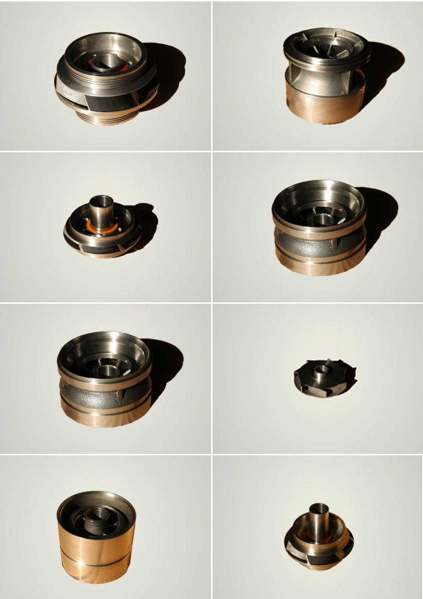
The impeller is shown in
Fig. 4 and the diffuser in
Fig 5.
Its geometry has the flow entering the impeller or diffuser parallel to the axis of the shaft and exiting perpendicular to the shaft, or in a "radial" direction. They are sometimes referred to as "pancake" or "mushroom" stages, respectively, because of the impellers’ flat shape and the diffusers’ mushroom-shaped downthrust pedestal. A cross-sectional schematic of a radial stage is shown in
Fig. 6.


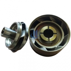
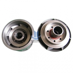
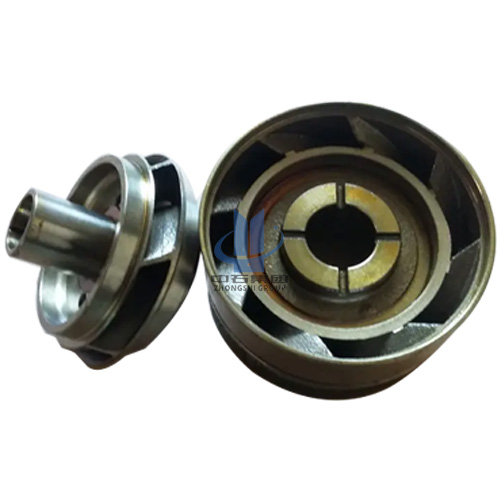
The second is a mixed-flow stage; a typical impeller is shown in
Fig. 7, and the diffuser is shown in
Fig. 8. Its geometry has the flow exiting the impeller at an angle less than 90° to the shaft. A graphic of this flow path is shown in
Fig. 9. Generally, this angle changes from near perpendicular to near axial, as the design flow rate of the stage increases for a particular-diameter unit. This relationship is shown in Fig. 10 .